Designing with Aluminium: Complete Guide to
Bespoke Extruded & Machined Aluminium Profiles
Aluminium profile design guide covering alloy selection (6xxx series), bespoke aluminium extrusion, aluminium profile machining, anodising and other finishing services, bespoke sub-assemblies, and customised packaging for tailor-made aluminium profiles under European (EN) standards.
1. Introduction: Purpose of This Guide & About ALUCAD
A good aluminium profile design is one that can be manufactured exactly as intended efficiently and consistently, at scale.
Many key decisions are made early in a project before all manufacturing constraints are fully visible, and small assumptions can actually have a pretty big impact on feasibility, cost, lead time, and final quality. So, in this guide, we'll walk through each stage of the manufacturing process and highlight important design choices which can affect how aluminium profiles are produced.
About ALUCAD
Before we get started, it's worth telling you a little about ALUCAD so you know who you're getting your aluminium profile design advice from.
ALUCAD is a bespoke aluminium profiles manufacturer, delivering read-to-install extruded and machined aluminium components intended for serial production. We operate across the full production chain, from early design support through to extrusion and aluminium finishing, in-house aluminium profile machining, sub-assemblies, packaging, and constant quality controls. Founded in 2000 by Laurent Hendrickx, we have worked in the end-to-end production management of bespoke aluminium profiles since the very beginning, having garnered a lot of insight and visibility into how design decisions translate into manufacturing outcomes.
This guide is a culmination of what we have learnt and what we've seen work and not work, with the goal of helping you get the result you’re aiming for first time round when designing with aluminium.
What this guide will help you do
This guide is intended as a practical design-for-manufacture reference.
It will help you to:
• Select appropriate alloys based on functional, aesthetic, and cost requirements
• Understand what bespoke aluminium extrusion can realistically achieve
• Identify when machining is required and how to design for it
• Anticipate constraints related to aluminium finishing and anodising
• Align design intent with European EN standards
Throughout the guide, we'll focus on the decisions which have the biggest impact on manufacturability. The aim is not to show what’s theoretically possible, but what can be produced reliably, repeatedly, and economically in serial production.
Standards and scope
All dimensional guidance and tolerance references in this document are based on European Norms (EN), with primary reference to EN 755 for extruded aluminium products (these are the standards we work with at ALUCAD, and therefore whatw e know best).
This guide does not replace formal standards documentation, detailed engineering drawings, or project-specific validation. It is intended to support decision-making and clearer communication with suppliers early in the project lifecycle.
2. Aluminium as a Material: Key Properties and Design Implications
Before getting into the manufacturing process, it’s worth starting with the material itself.
Aluminium is used for extruded profiles because it strikes a strong balance between weight, performance, and manufacturability. Aluminium’s properties don’t just sit in the background. They directly shape how your profile should be designed, produced, and how it will behave in use.
Not all of these properties will matter equally for your component, but understanding them upfront helps you focus on what will impact your design.
Density and weight
Aluminium has a density of approximately 2.7 g/cm³, around one third that of steel.
This makes it an obvious choice when weight reduction matters. Lower weight helps to reduce loads on supporting structures, improve handling and assembly, and it lowers the energy consumption in transport or use.
That said, pushing weight reduction too far (by thinning walls or removing material) can create issues with stiffness, extrusion stability, and tolerance control. There’s always a balance.
Strength and stiffness
Aluminium comes in a wide range of strengths depending on the alloy and temper. However, aluminium is less stiff than steel, so even at higher strengths, it will deflect more under the same load.
For extruded profiles, stiffness is driven far more by geometry than by material strength. In most cases, increasing section depth or redistributing material is more effective than switching to a higher-strength alloy. Simply choosing a stronger alloy without changing the geometry rarely fixes deflection, and it can make extrusion and finishing more difficult.
Thermal behaviour
Aluminium expands relatively quickly with temperature (around 23 µm per meter per °C).
This becomes important in long profiles, assemblies with tight interfaces, and applications exposed to temperature variation. You need to account for aluminium’s thermal behaviour when defining clearances, assembly fits, and tolerances over length.
Ignoring thermal expansion early on often leads to misalignment and functional issues that can’t be solved just by tightening tolerances later.
Corrosion resistance
Aluminium naturally forms a protective oxide layer when exposed to air. This gives it good corrosion resistance in most environments.
In neutral or mildly corrosive conditions, no additional protection is often needed. In more aggressive environments (acidic, alkaline, or marine), you’ll need to think about alloy selection, surface treatment, and design considerations, too.
Machinability and formability
Aluminium is easy to machine and form. Cutting forces are low, tool wear is limited, and most operations can be done efficiently. This makes it ideal for adding functional features where extrusion alone isn’t enough.
That said, machining should add value and not fix avoidable design issues. If a feature can be integrated into the extrusion, it’s usually more cost-effective and more consistent in production.
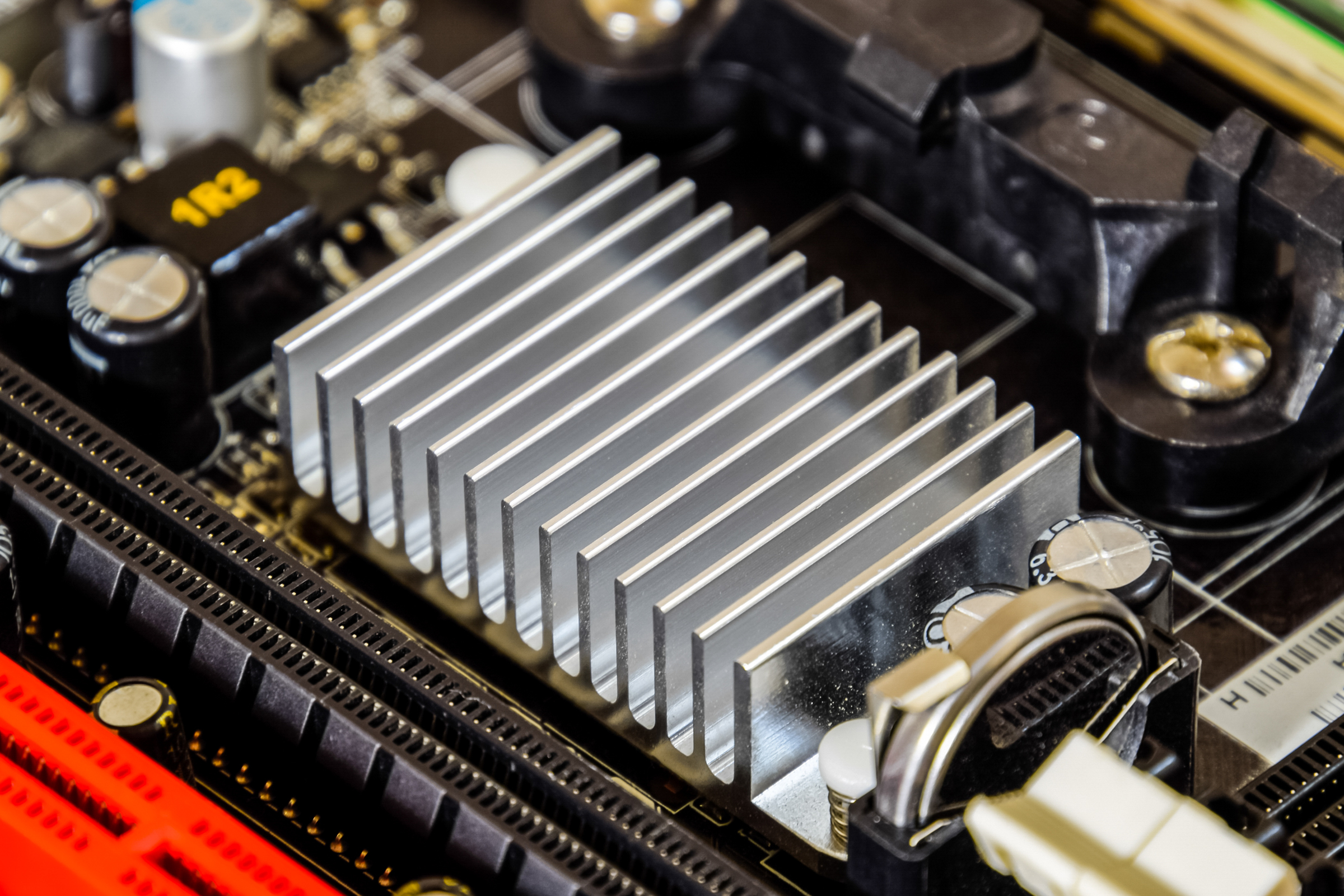
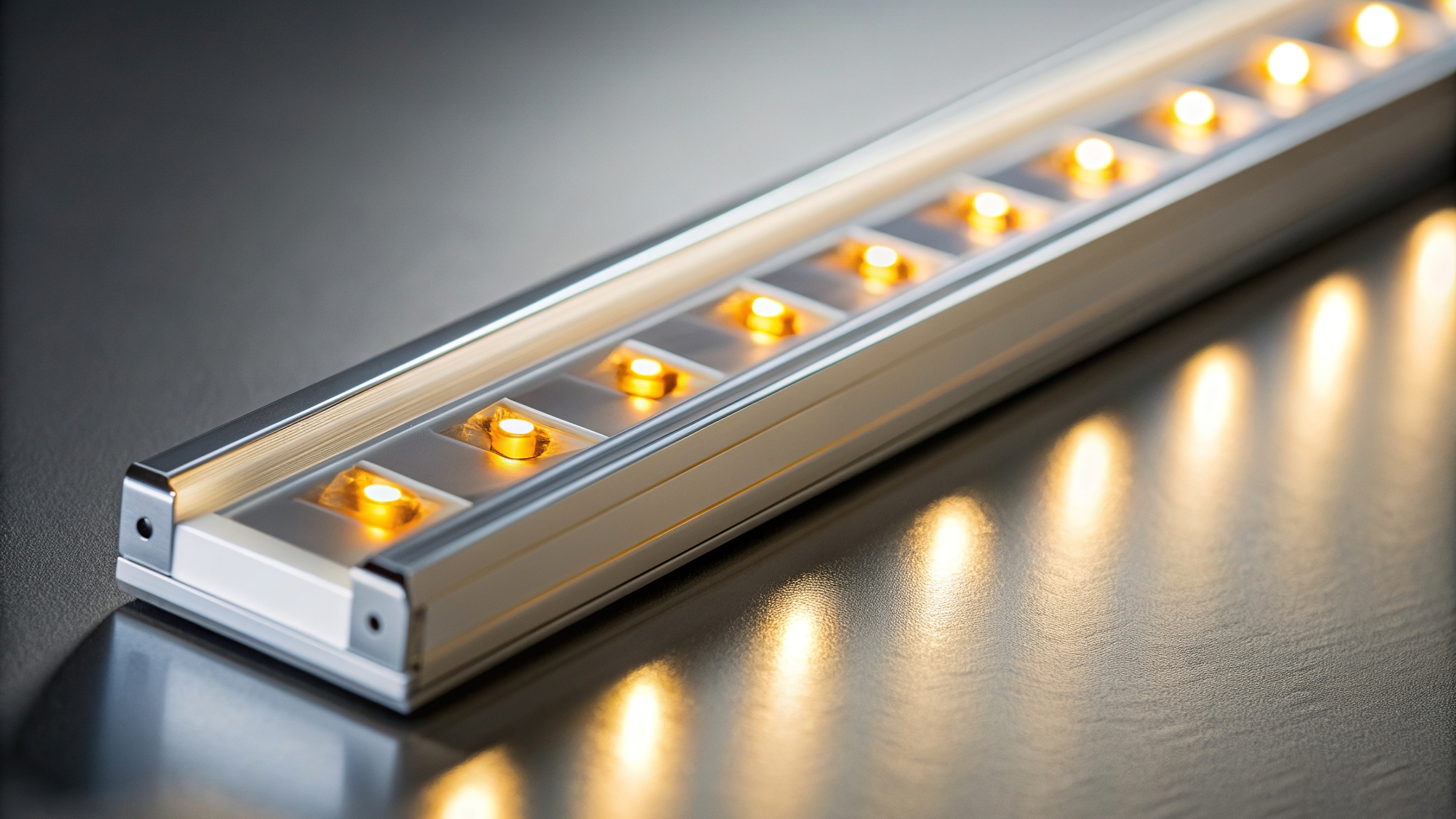
Thermal and electrical conductivity
Aluminium has high thermal and electrical conductivity relative to its weight. It’s well suited for heat dissipation, thermal management, and electrical applications.
In these cases, geometry matters as much as material. Surface area, wall thickness, and airflow often have a bigger impact than alloy choice alone.
Durability and sustainability
Aluminium holds its properties over long service lives and can be recycled indefinitely without loss of performance.
Recycling also requires far less energy than primary production, which makes it a strong choice for long-life or high-volume products, especially when designs are stable and repeatable.
Key takeaways
• Aluminium allows for lightweight, efficient designs
• Stiffness is driven more by geometry than by strength
• Thermal expansion needs to be considered early
• Corrosion resistance is strong, but environment and finishing still matter
• Aluminium machines easily, but machining should add function, not compensate for design
• Geometry plays a major role in thermal and electrical performance
3. 6xxx-Series Aluminium Alloys
Before getting into the design of your bespoke aluminium profile, it’s important to understand the various aluminium alloys and which will best suit your performance requirements.
Pure aluminium is relatively soft. To make it suitable for real applications, it’s alloyed with small amounts of other elements. These additions directly affect strength, extrudability, machinability, surface finish, and ultimately, cost. In other words, the alloy you choose affects both performance and how easily the profile can be manufactured.
There are many aluminium alloys available, but only a small number are truly well suited to extrusion. Fewer still perform consistently across the full production process.
In practice, most bespoke extruded profiles use 6xxx-series aluminium alloys. When working to European EN standards, these alloys offer the most reliable balance between performance, manufacturability, and surface quality. At ALUCAD, we primarily work with 6060, 6063, 6005, 6061, and 6082, which we’ll look at in more detail below.
Why 6xxx-series alloys are preferred
6xxx-series alloys are aluminium–magnesium–silicon alloys. During heat treatment, magnesium and silicon combine to form magnesium silicide, which gives these alloys their useful combination of properties.
In practical terms, this allows them to:
• flow reliably through extrusion dies
• respond predictably to heat treatment
• offer a useful range of strengths
• work well with anodising and common surface finishes
This balance is what makes them the default choice for most industrial and technical applications. They may not be the strongest alloys available, but they are among the most consistent and reliable in production.
6xxx-series alloys’ properties
The alloys below represent the standard range used at ALUCAD for bespoke extruded profiles. Each has clear advantages and limitations that should be understood at the design stage.
6060
Typically used for thin-walled, aesthetic, anodised profiles.
Composition
• Silicon: 0.30–0.60%
• Magnesium: 0.35–0.60%
• Iron: 0.10–0.30%
• Manganese: 0.10% max
• Chromium: 0.05% max
• Copper: 0.10% max
• Titanium: 0.10% max
• Zinc: 0.15% max
• Other elements: 0.05% max each, 0.15% max total
• Aluminium: remainder
Characteristics
• Excellent surface quality after extrusion
• Very good anodising appearance
• Well suited to complex or thin geometries
Limitations
• Lower mechanical strength
• Less suitable for heavily machined or load-bearing parts
Cost perspective
Often the most economical option for visually critical components where strength requirements are moderate.
6063
Typically used for general-purpose technical and semi-architectural profiles.
Composition
• Silicon: 0.20–0.60%
• Magnesium: 0.45–0.90%
• Iron: 0.35% max
• Copper: 0.10% max
• Manganese: 0.10% max
• Chromium: 0.10% max
• Zinc: 0.10% max
• Titanium: 0.10% max
• Other elements: 0.05% max each, 0.15% max total
• Aluminium: remainder
Characteristics
• Good balance between surface quality and strength
• Widely used and well understood
• Reliable anodising results
Limitations
• Not intended for high structural loads
• Strength is often overestimated in mechanical applications
Cost perspective
A versatile and cost-effective choice where machining and strength demands remain moderate.
6005
Typically used for thicker sections with higher load requirements.
Composition
• Silicon: 0.50–0.90%
• Magnesium: 0.40–0.70%
• Iron: 0.35% max
• Copper: 0.30% max
• Manganese: 0.50% max
• Chromium: 0.30% max
• Zinc: 0.20% max
• Titanium: 0.10% max
• Other elements: 0.05% max each, 0.15% max total
• Aluminium: remainder
Characteristics
• Higher mechanical strength than 6060 and 6063
• Suitable for structural or load-bearing profiles
• Accepts machining reasonably well
Limitations
• Reduced surface quality for aesthetic finishes
• Anodising appearance is typically less uniform
Cost perspective
Slightly higher extrusion cost due to thicker sections and lower extrusion speeds, but often avoids the need to move to higher-strength alloys.
6061
Typically used for machined, mechanically loaded components.
Composition
• Silicon: 0.40–0.80%
• Magnesium: 0.80–1.20%
• Iron: 0.70% max
• Copper: 0.15–0.40%
• Manganese: 0.15% max
• Chromium: 0.04–0.35%
• Zinc: 0.25% max
• Titanium: 0.15% max
• Other elements: 0.05% max each, 0.15% max total
• Aluminium: remainder
Characteristics
• Good mechanical strength
• Very good machinability
• Well suited to parts where function is prioritised over appearance
Limitations
• More demanding to extrude than 6060 or 6063
• Surface finish and anodising appearance are generally less consistent
Cost perspective
Often selected where machining performance and mechanical function matter more than aesthetic looks or extrusion efficiency.
6082
Typically used for strength-driven designs.
Composition
• Silicon: 0.70–1.30%
• Magnesium: 0.60–1.20%
• Iron: 0.50% max
• Copper: 0.10% max
• Manganese: 0.40–1.00%
• Chromium: 0.25% max
• Zinc: 0.20% max
• Titanium: 0.10% max
• Other elements: 0.05% max each, 0.15% max total
• Aluminium: remainder
Characteristics
• Highest mechanical strength among commonly extruded 6xxx-series alloys
• Suitable for mechanically demanding applications
Limitations
• Reduced extrudability
• Poor surface treatment quality
• Higher sensitivity to distortion
Cost perspective
Typically higher extrusion and finishing cost. Should be selected only where strength requirements clearly justify the trade-offs.
ALUCAD production note
6082 is not part of ALUCAD’s standard alloy range but can be supplied for suitable projects and volumes, subject to technical validation.
6xxx alloys comparison
Alloy |
Typical use |
Strength |
Extrudability |
Anodised appearance |
Machinability |
Notes |
|---|---|---|---|---|---|---|
6060 |
Architectural profiles, visible parts |
Medium-low |
High |
High |
Medium |
Best surface quality; ideal for complex thin-wall extrusions. |
6063 |
Architectural profiles, anodised finishes |
Medium-low |
High |
High |
Medium |
Common “architectural alloy”; slightly higher strength than 6060. |
6005 |
Structural profiles, frames, rails |
Medium |
Medium |
Medium |
Medium |
Good all-rounder for structure; surface less “aesthetic” than 6060/6063. |
6061 |
Machined, mechanically loaded components |
Medium-high |
Medium |
Low |
High |
Strength-focused; anodised appearance typically less uniform than 6060/6063. |
6082 |
Structural + heavily machined parts |
High |
Medium-low |
Low |
High |
Very common in Europe; strong and stable, but not the best for decorative anodising. |
Alloy choice and downstream processes
Alloy selection affects more than mechanical performance. It also influences:
• extrusion speed and process stability
• die wear and tooling cost
• machining behaviour
• anodising appearance and consistency
• distortion risk during production
Selecting an alloy without considering the full production chain often leads to compromises later in the project that are difficult or costly to resolve.
The most frequent issues encountered during alloy selection include:
• choosing high-strength alloys where geometry could achieve the same result
• expecting an aesthetic look from structural alloys
• over-specifying strength without a clear need
A good way to think about it:
• If appearance matters → start with the right alloy and design for strength
• If strength matters → accept the trade-offs in finish and cost
Temper condition: strength is not defined by alloy alone
When designing with aluminium, specifying the alloy is only part of the decision. The temper condition (T5, T6, etc.) defines the heat treatment state of the material and has a direct impact on strength, ductility, stability and machining behaviour.
For 6xxx series extrusion alloys, the most common tempers are T5 and T6:
• T5 means the profile is cooled from the extrusion temperature and then artificially aged to increase strength. It is not solution heat treated after extrusion.
• T6 means the profile is solution heat treated, quenched and artificially aged to achieve higher mechanical strength.
T6 temper provides higher yield and tensile strength compared to T5. However, that increase in strength comes with reduced elongation at break, meaning the material is less ductile. In thin sections, snap-fit features or impact-sensitive designs, that reduction in ductility can be relevant.
T6 can also introduce higher internal stresses due to quenching during solution heat treatment. In profiles that require extensive machining, this can increase the likelihood of minor movement after material removal. In contrast, T5 often offers slightly better dimensional stability in less demanding structural applications.
From a machining perspective, T6 typically provides cleaner cutting behaviour because of its higher hardness, while softer tempers may exhibit more material smearing under certain cutting conditions.
Temper selection should therefore align with:
• structural load requirements
• required yield strength
• ductility and elongation needs
• machining intensity
• dimensional stability expectations
In aluminium profile design, the correct temper is the one that delivers sufficient strength without introducing unnecessary brittleness, distortion risk or processing complexity. Alloy and temper must be specified together to ensure the profile performs as intended in both production and service.
Key takeaways
• Most bespoke aluminium profiles are produced using 6xxx-series alloys
• Alloy choice affects the entire production process
• High strength and high surface quality rarely come together
• Geometry is often more effective than increasing strength
• Temper (T5 vs T6) significantly affects behaviour
• Getting alloy and temper right early avoids costly redesign
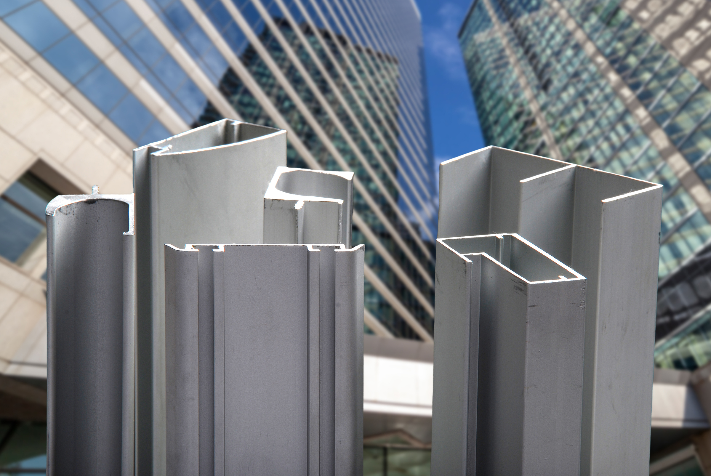
4. Principles of Aluminium Extrusion
When designing bespoke aluminium profiles, understanding the extrusion process is essential, as it directly shapes how your part will be manufactured.
Aluminium extrusion is a forming process and should not be expected to produce tight positional or dimensional precision. Many issues in bespoke aluminium extrusion come from expecting that level of accuracy from a process where some dimensional variation is inherent.
If you understand what extrusion can and cannot do, you can design aluminium profiles that are easier to produce, more consistent, and more cost-effective.
This section of the aluminium extrusion design guide focuses on the key engineering principles that have the greatest impact on quality, tolerances, lead time, and cost.
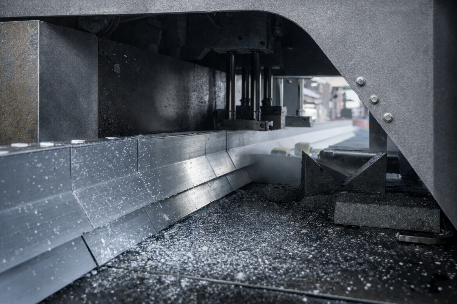
What aluminium extrusion involves
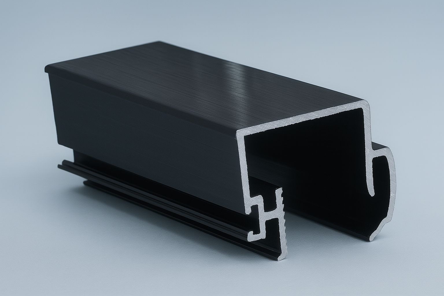
Aluminium extrusion is a hot forming process. A heated aluminium billet is pushed through a steel die under high pressure, creating a continuous profile with a fixed cross-section.
After extrusion, the profile is:
• cooled and quenched (aging)
• stretched to ensure straightness and reduce internal stresses (tensioning)
• cut to length (press cutting)
Because the material is flowing under heat and pressure, the final result is influenced by:
• profile geometry
• alloy selection
• die design
• press size and applied pressure
• extrusion speed and cooling conditions
This is why extrusion standards such as EN 755 define tolerance ranges, not absolute precision.
Press size and pressure versus profile diameter
Your bespoke aluminium profile design determines how easily your profile can be produced.
The key relationship is between circumscribed diameter, wall thickness, and overall geometry.
Designs that combine small diameters with very thin sections are inherently more sensitive to variation. For example, a profile with a circumscribed diameter of around 45 mm and wall thicknesses close to 1 mm will be significantly more difficult to extrude consistently than a larger or more balanced design.
In practice, this can lead to distortion, uneven material flow, surface defects, and reduced dimensional consistency.
If your design requires very thin sections, increasing the overall size or adjusting the geometry will often improve stability.
The next sections look in more detail at wall thickness, symmetry, and other design factors that influence extrusion behaviour.
Wall thickness balance
Wall thickness is one of the most important design variables in extrusion. Very thin walls are possible, but they increase risk and reduce process stability.
Good design practice includes:
• Avoiding extreme minimum wall thicknesses
• Keeping wall thickness as uniform as possible
• Avoiding abrupt transitions between thin and thick sections
Large thickness variations cause uneven metal flow, which leads to distortion, tolerance variation, and reduced surface quality.
Symmetry and flow balance
Symmetrical profiles extrude more predictably because aluminium flow is balanced across the die.
Asymmetrical profiles increase:
• twist and bow
• sensitivity to cooling conditions
• difficulty maintaining tight tolerances
Material is often added to balance metal flow across different areas of the die. For tolerance control, flow balance is often more important than minimising material.
Cantilever length and die-side adjustments
Cantilever length refers to the unsupported length of profile elements extending from the die. If they are too long or too thin, they become unstable during extrusion.
Excessive cantilever length can cause:
• deflection during extrusion
• flow instability
• poor dimensional repeatability
Adjusting cantilever length is one of the most common die-side changes during extrusion development. These adjustments are made to improve flow control and stability, not to increase strength. When an extruder requests cantilever modifications, it is almost always to improve tolerance consistency and production robustness.
Tolerances under EN 755 standards
A common misunderstanding is treating extrusion as a precision process. Often, we see unnecessarily tight tolerances on as-extruded features, which rarely improves functional performance, significantly increases extrusion difficulty, and it increases inspection time, and thereby cost.
Over-specified tolerances can multiply profile cost without adding value. Where positional accuracy, flatness, or tight dimensional control are functionally critical, those features should be defined for machining.
EN 755 defines dimensional tolerances, limits for straightness, twist, and bow, and general flatness expectations. These limits reflect what is realistically achievable in extrusion.
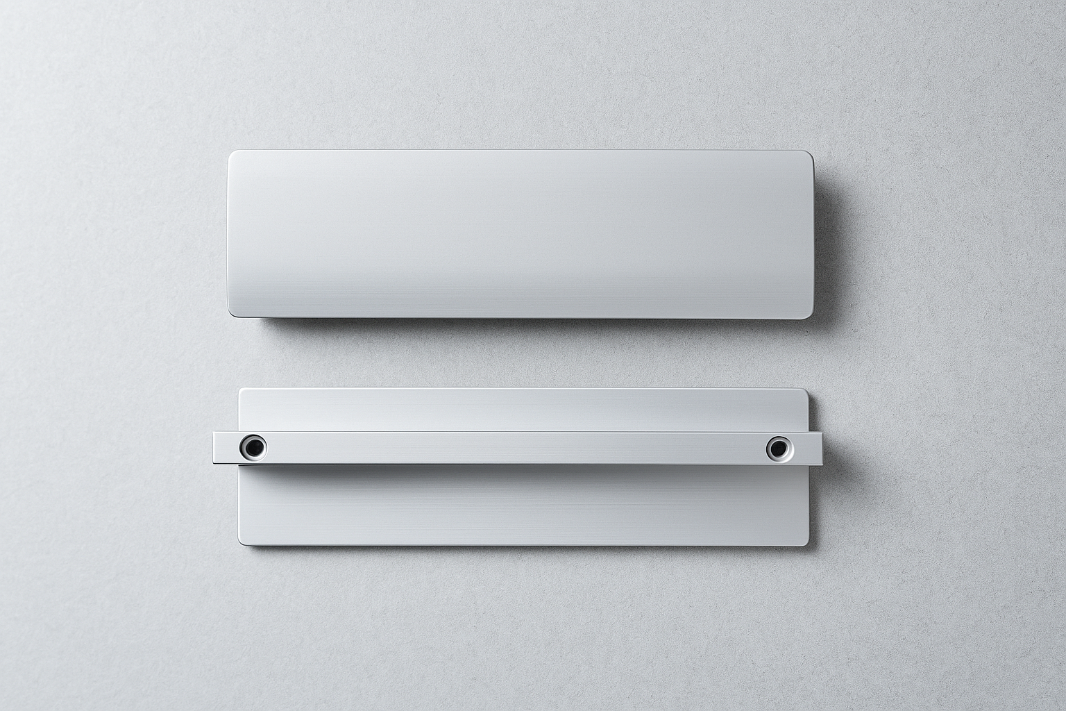
Surface quality and flat faces
Long, uninterrupted flat faces tend to show extrusion lines and flow marks, which become more visible after anodising.
To manage aesthetic expectations:
• Avoid large flat surfaces where possible
• Introduce ribs, radii, or surface features
• Recognise that perfectly flat surfaces usually require post-processing
Polishing prior to anodising can reduce visible variation, but minor differences will still remain.
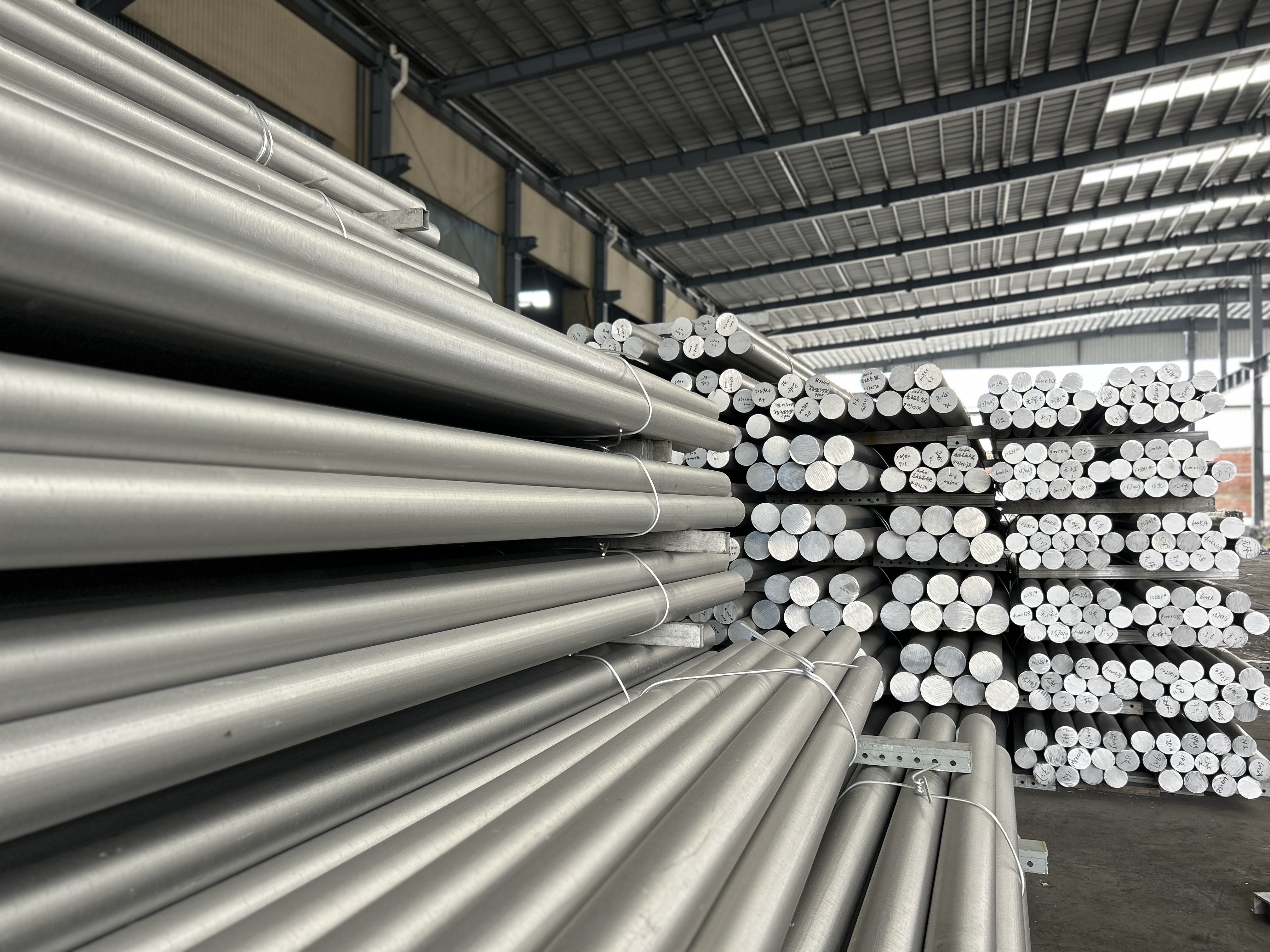
Solid vs hollow profiles
Solid profiles
Solid profiles contain no enclosed voids. In practice, fully solid sections are rarely optimal for serial production. They increase material usage, weight, extrusion force, and handling effort without necessarily improving functional performance.
Solid sections are typically justified only where:
• internal cavities would compromise function
• load paths or interfaces cannot accommodate hollows
Hollow profiles
Hollow profiles contain one or more enclosed voids and are produced using bridge or porthole dies.
Where functionally possible, hollow sections are generally preferred because they:
• reduce profile weight
• improve handling and process stability
• often reduce extrusion force
• maintain functional performance when properly designed
• do not typically increase tooling cost
The longitudinal weld seams formed during hollow extrusion are metallurgically sound and fully covered by EN standards. Where relevant, their position is considered during design to avoid functional or aesthetic impact.
Solid profiles should not be used by default. Hollowing a profile is often the most effective way to improve both manufacturability and cost efficiency.
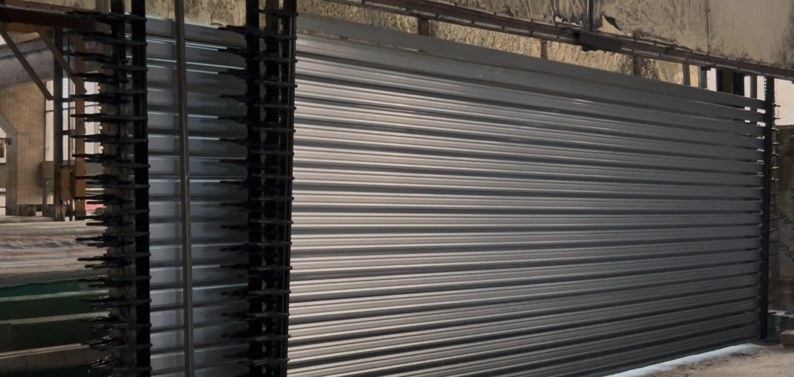
ALUCAD production note
At ALUCAD, typical maximum extruded profile lengths are approximately 5,850 mm, primarily to ensure compatibility with container transport and downstream handling.
Key takeaways
• Aluminium extrusion is a forming process, not precision machining
• Profile geometry directly controls manufacturability
• Balanced wall thickness and symmetry improve consistency
• Flow stability matters more than minimising material
• Tight tolerances increase cost without improving results
• Design for extrusion first, then machine where needed
• Surface quality must be considered during design
• Hollow sections are often more efficient than solid ones
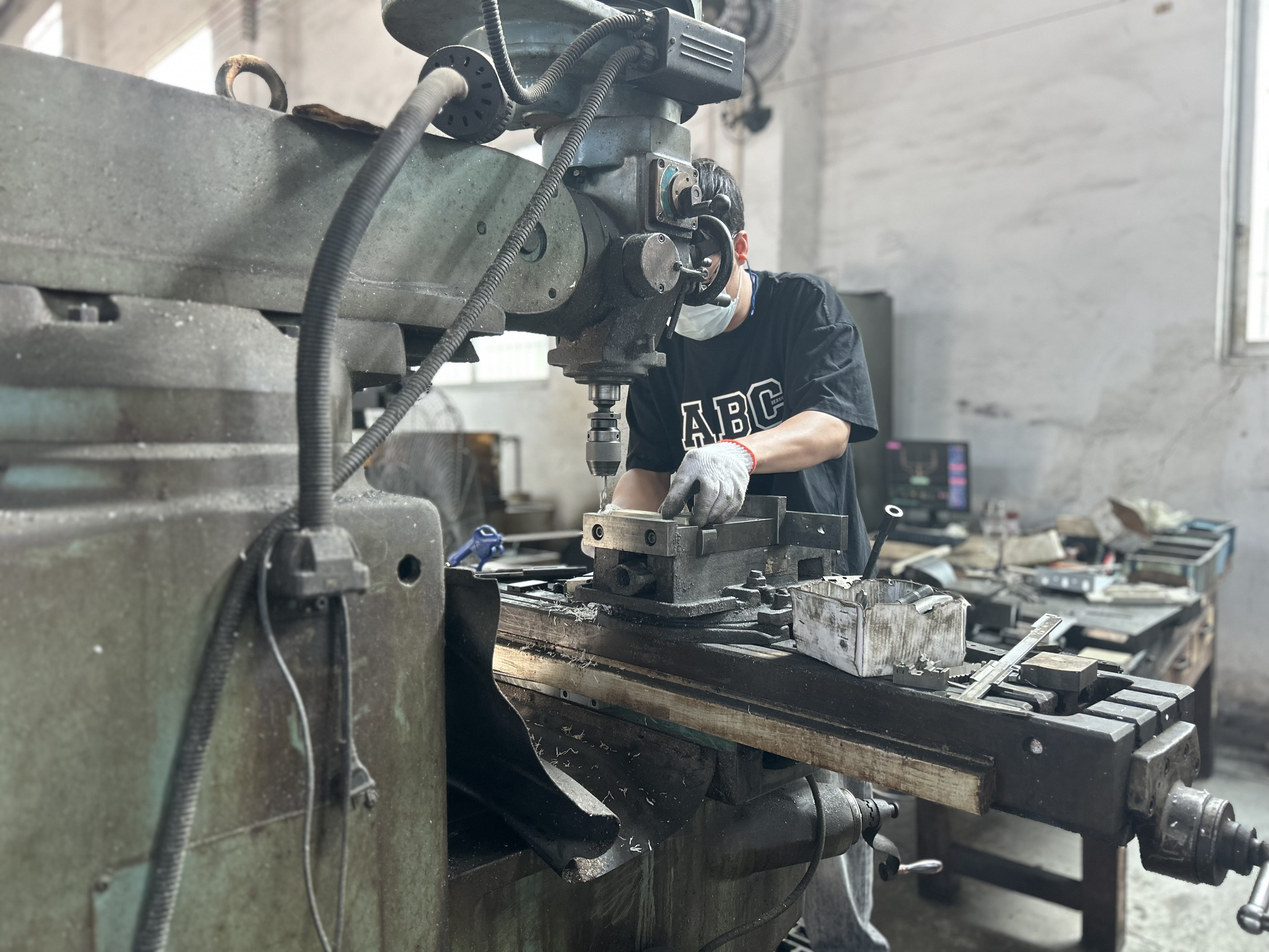
5. Principles of Aluminium Profile Machining
Extrusion will give your bespoke aluminium profile the cross-section, and machining will create the features that control assembly, alignment, interfaces, and precision. Machining isn’t there to “improve” an extruded profile. It’s there to define function.
Extrusion works within EN-defined tolerances, but it doesn’t control precise relationships between features. Machining does. When machining aluminium extrusions, you’re defining how parts locate during assembly, where loads are transferred, how interfaces fit/seal, and which surfaces are used for inspection.
Extrusion is for shape, machining is for function.
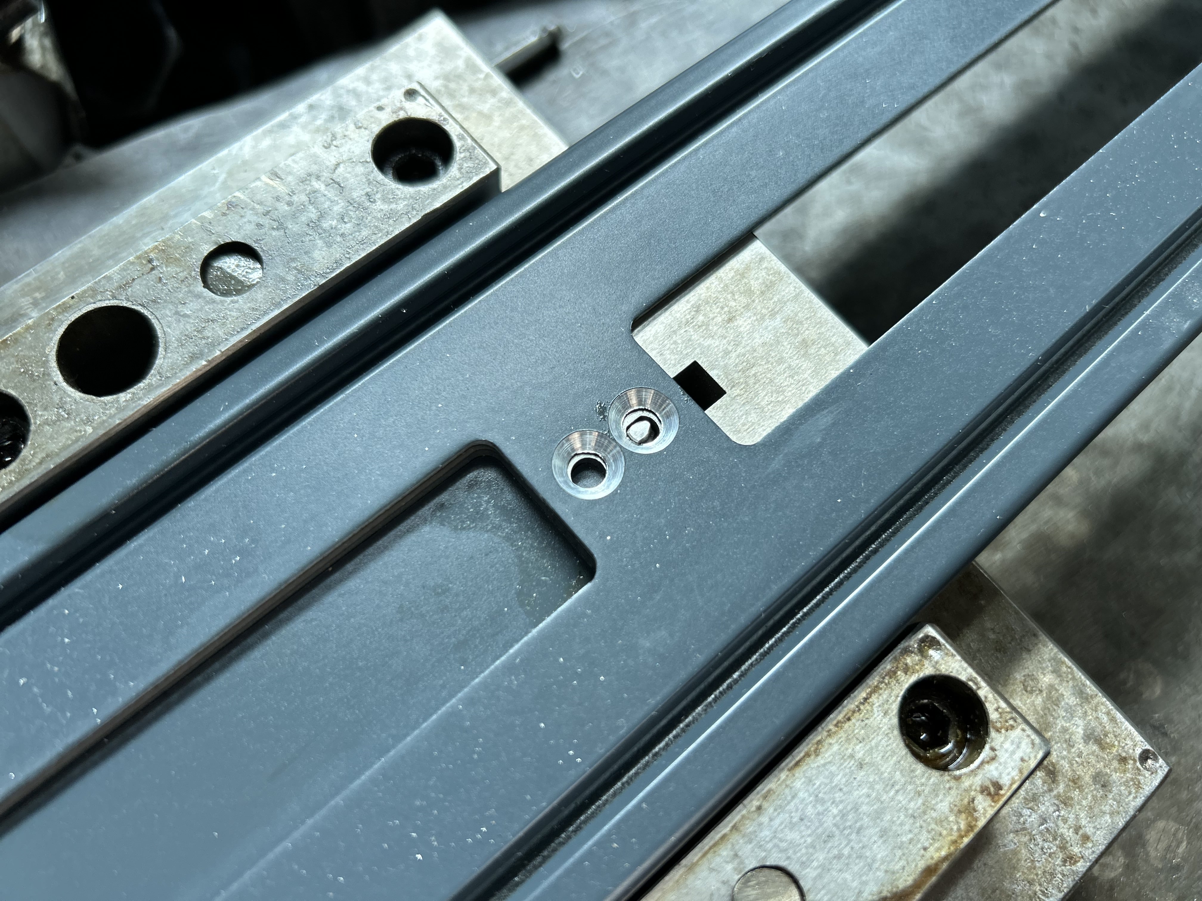
Using machining to control accuracy (datums)
Don’t rely on as-extruded surfaces for functional alignment. Extrusion introduces natural variation—straightness, twist, wall thickness, and profile distortion. Even when individual parts are within tolerance, these small deviations accumulate during assembly (tolerance stack-up), leading to misalignment and poor fit.
To control this, a datum strategy is required.
A datum strategy defines which surfaces or features are used as reference points for all machining and measurement. This ensures consistency between design intent and manufacturing.
In practice:
• Critical surfaces are machined first to create stable references
• These references (datums) are then used to position and machine all other features
Typically, three datums are used:
• A primary datum to establish the main locating surface
• A secondary datum to control rotation
• And a tertiary datum to fully constrain the part
Datums are about ensuring everyone involved in the production of your bespoke aluminium profile is referencing the same geometry.
Machining setup strategy: reduce re-clamping
Every time a part is repositioned, variation increases.
When machining aluminium profiles, aim to:
• machine critical features in as few setups as possible
• keep reference faces consistent
• avoid unnecessary machining on multiple sides
Designs that require frequent re-orientation are harder to control, take longer to produce, and increase the cost and potential variability.
If a feature can be moved onto a common machining face without affecting function, then it's best to do it that way.
Profile stiffness and machining behaviour
Extruded profiles are often long and relatively flexible. During machining, cutting forces can cause:
• deflection
• dimensional drift
• surface quality issues
This is where extrusion design directly affects machining performance. So it's important to consider reinforcing areas which will be machined, avoiding long and unsupported features, and balancing material distribution.
Even small changes like adding a rib, adjusting wall thickness, or introducing a hollow, can significantly improve machining stability.
Designing extrusion with machining in mind
In practice, improving the extrusion often reduces machining time more effectively than adding machining steps.
Typical design improvements:
• adjust wall thickness to reduce movement
• improve symmetry for stable clamping
• reduce cantilevered features
• remove unnecessary material where possible
Machining sequence and dimensional stability
Machining releases internal stresses from extrusion and cooling. This can cause slight movement, particularly in:
• long profiles
• asymmetrical sections
• profiles with significant material removal
These effects are controlled through:
• defined machining sequences
• balanced material removal
• controlled clamping and support
Critical features are always machined after stabilising operations, not before.
The order of operations matters, and your design can make that easier or harder.
Custom tooling and fixtures
Standard cutting tools are designed for generic parts. Bespoke aluminium profiles rarely behave like generic parts.
Purpose-built tooling and fixtures allow:
• tighter tolerances over long production runs
• multiple features to be machined in a single operation
• reduced cycle time without increased risk
• improved surface quality on complex geometries
• earlier detection of wear or dimensional drift
Because tooling can be adapted quickly, iteration cycles are shorter and break-even volumes are lower than is often assumed. Custom tooling is therefore used where it improves total production efficiency, not only at very high volumes. It's not often an option given by suppliers because they need to fabricate the tool elsewhere, increasing time and costs, but if the supplier is equiped to produce a custom tool for your bespoke aluminium profile, most of the time, it's worth it.
Find out more about custom tooling for bespoke aluminium profiles.
ALUCAD production note
Custom machining tools and fixtures are designed and produced in-house. This reduces the time and cost typically associated with external tooling development, resulting in more efficient and cost-effective machining and production of extruded aluminium products.
Common machining-related design mistakes
The most common issues we see in designs when bespoke aluminium profiles requiring machining are:
• Applying tight tolerances to non-functional features
• Distributing tight tolerances across multiple unrelated faces
• Designing profiles that require machining on every side
• Treating machining as a corrective step rather than a design tool
Key takeaways
• Machining defines how a profile functions and assembles
• Controlled datum surfaces matter more than global tight tolerances
• Fewer setups improve consistency and reduce cost
• Small extrusion changes often reduce machining effort significantly
• Custom tooling improves precision, speed, and repeatability
6. Anodisation & Other Surface Treatments
Aluminium finishing should be determined early during profile design, alongside alloy selection, extrusion quality, and machining strategy. There are a lot of factors, like alloy choice, profile geometry, machining sequence, which directly influence which surface finishes are achievable, how consistent they will be in production, and at what cost.
What is aluminium anodisation
Anodisation is an electrochemical process that converts the surface of aluminium into a controlled oxide layer.
The anodised layer will:
• improve corrosion resistance
• increase surface hardness
• allow for colouring, depending on alloy and process
• reduce electrical conductivity at the surface
• slightly reduces thermal conductivity at the surface compared to bare aluminium
Anodising is not a coating. The oxide layer grows from the aluminium itself, which means surface condition before anodisation is criticial, and alloy composition directly affects appearance. It also doesn't hide defects. Die lines, flow marks, scratches, and machining marks remain visible and are often accentuated. If a surface must appear uniform after anodising, it must already be uniform beforehand.
Alloy choice and anodising appearance
Not all aluminium alloys anodise in the same way.
Alloys optimised for surface quality, such as 6060 and 6063, typically produce more uniform colour and cleaner, more consistent appearance.
Higher-strength alloys, such as 6061 and 6082, often show colour variation, streaking or patchiness, and are more sensitive to process variations.
Pursuing aesthetic anodised finishes on structural alloys frequently leads to additional processing, rework, or rejection without improving functional performance. If appearance is critical, alloy selection must prioritise anodising behaviour early, even if this requires accepting lower mechanical strength and compensating through geometry.
Anodising before or after machining
Pre-machining anodising
The profile is anodised first, then machined.
Advantages:
• Uniform anodised finish on visible extruded faces
• Lower anodising cost
• Suitable when machined areas are hidden or aesthetic is not critical
Limitations:
• Machined surfaces remain un-anodised / visible colour contrast between anodised and raw aluminium
Post-machining anodising
The profile is fully machined, then anodised.
Advantages:
• Anodised finish on all faces
• Best aesthetic consistency on finished parts
Limitations:
• Higher cost
• Additional handling and process steps
• Tighter control required on dimensions and surface condition
Post-machining anodising should be reserved for parts where full aesthetic consistency is functionally or commercially justified.
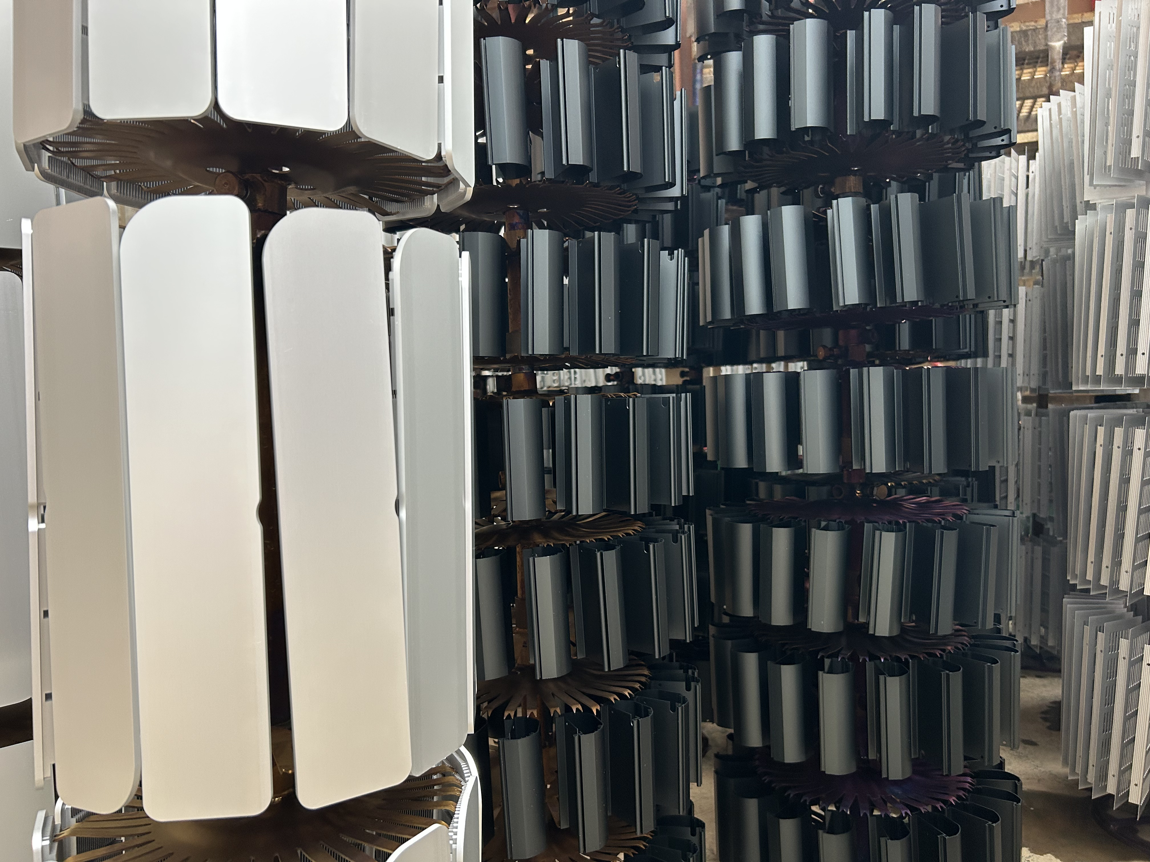
Contact points, racking, and handling during anodising
During anodising, profiles must be electrically connected and mechanically supported. This requires contact points, which will leave visible marks. These marks are unavoidable.
When anodising is carried out before machining, additional material can be allowed so that contact areas are later removed. For long profiles, additional support points may be required.
When anodising is carried out after machining, contact marks remain on the finished part and must be planned for in the design.
Other surface treatments
Polishing
• Improves surface appearance before anodising or coating
• Adds processing time and cost
• Best reserved for visible, high-value surfaces
Lacquering / powder coating
• Offers greater colour flexibility than anodising
• More forgiving of minor surface variation
• Adds coating thickness that must be considered in tolerance definition
Sanding, sandblasting / surface preparation
• Used to reduce extrusion lines or machining marks
• Improves surface uniformity and appearance
• Adds processing time and cost
• Requires controlled, consistent application to avoid uneven results
Key takeaways
• Surface finishing outcomes are determined early in the design
• Anodising improves protection but highlights surface defects
• Alloy choice strongly influences anodising appearance
• Pre-machining anodising leaves cut surfaces raw; post-machining anodising leaves contact marks
• Contact marks for post-machining anodising are unavoidable and must be designed for
• Early finish selection avoids rework and unnecessary cost
• Improves surface appearance before anodising or coating
• Adds processing time and cost
• Best reserved for visible, high-value surfaces
• Offers greater colour flexibility than anodising
• More forgiving of minor surface variation
• Adds coating thickness that must be considered in tolerance definition
Sanding, sandblasting / surface preparation
• Used to reduce extrusion lines or machining marks
• Improves surface uniformity and appearance
• Adds processing time and cost
• Requires controlled, consistent application to avoid uneven results
Key takeaways
• Surface finishing outcomes are determined early in the design
• Anodising improves protection but highlights surface defects
• Alloy choice strongly influences anodising appearance
• Pre-machining anodising leaves cut surfaces raw; post-machining anodising leaves contact marks
• Contact marks for post-machining anodising are unavoidable and must be designed for
• Early finish selection avoids rework and unnecessary cost
• Used to reduce extrusion lines or machining marks
• Improves surface uniformity and appearance
• Adds processing time and cost
• Requires controlled, consistent application to avoid uneven results
• Surface finishing outcomes are determined early in the design
• Anodising improves protection but highlights surface defects
• Alloy choice strongly influences anodising appearance
• Pre-machining anodising leaves cut surfaces raw; post-machining anodising leaves contact marks
• Contact marks for post-machining anodising are unavoidable and must be designed for
• Early finish selection avoids rework and unnecessary cost
7. Assembly, Packaging & Delivery
Assembly, packaging, and delivery are often treated as downstream activities. In practice, they are a direct continuation of the design process. Profiles that are designed with assembly and transport in mind are easier to handle, less prone to damage, and more economical to deliver.
For this reason, these stages should be considered early, alongside extrusion, machining, and finishing—not as add-ons at the end of the project.
Assembly considerations
Depending on project requirements, profiles may be supplied as:
• Individual machined components
• Sub-assemblies
• Fully assembled units
• Assemblies integrating aluminium and non-aluminium parts
Assembly operations typically include:
• Mechanical fastening
• Insertion of hardware
• Alignment and functional checks
• Preparation for direct installation
For serial or repeat assemblies, integrating assembly operations upstream reduces handling, assembly errors, and internal labour at the customer’s facility, while enabling earlier detection of defects and faster corrective action. In many cases, this lowers total landed cost by simplifying logistics and reducing rework.
Designing profiles for efficient assembly
Profiles that assemble reliably tend to share the same design principles:
• Clearly defined datum surfaces
• Accessible and logically positioned fixing points
• Consistent interfaces and hole patterns
• Tight tolerances applied only where they affect function
Assembly issues frequently arise from over-constrained designs, where multiple tight tolerances interact unnecessarily. If two parts must fit together, one feature should control the fit. Other related dimensions should be allowed to float within realistic limits.
Designing for assembly is primarily about controlling interfaces, not tightening every dimensional tolerance.
Packaging considerations
Packaging should be designed around the part and the transport conditions. It is not a generic solution.
Packaging requirements depend on:
• Profile length and stiffness
• Surface finish (raw, anodised, polished, coated)
• Assembly state (individual parts or assemblies)
• Transport method and distance
Effective packaging typically combines:
• Protective films where appropriate
• Spacers or separators to prevent contact
• Crates or pallets designed for the specific geometry
Finished surfaces—particularly anodised, polished, or coated parts—are sensitive to:
• Abrasion
• Contact marks
• Vibration during transport
Packaging design must therefore consider:
• Contact points between parts
• Stackability
• Movement during handling and transport
Addressing these points early reduces transit damage, disputes, and rework at far lower cost than replacing damaged components.
Key takeaways
• Assembly, packaging, and delivery are extensions of the design process
• Upstream assembly can reduce total cost and operational complexity
• Clear datum strategy improves assembly yield and consistency
• Packaging must be matched to surface finish and transport conditions
8. Design Checklist Before Sending an RFQ
Before requesting a quotation for a bespoke extruded aluminium product, reviewing the points below will significantly improve quotation accuracy, technical feasibility, lead time, and final part quality.
This checklist is intended for both engineers and buyers. It reflects the most common causes of redesign, cost increase, and delay observed when aluminium profiles are not designed with manufacturing reality in mind.
1. Material and alloy selection
• Is the selected alloy appropriate for both mechanical requirements and surface finish expectations?
• Are aesthetic requirements compatible with the chosen alloy?
• Has stiffness been optimised through geometry before selecting a higher-strength alloy?
• Are machinability and distortion risk acceptable for the selected alloy?
• Will surface treatment (e.g. anodising) affect thermal or electrical performance?
2. Profile geometry and extrusion design
• Are wall thicknesses balanced and realistic for stable extrusion?
• Is the profile as symmetrical as function allows to promote balanced metal flow?
• Have unnecessary solid sections been hollowed where function allows?
• Are cantilever lengths controlled to reduce flow instability and distortion?
• Are sharp internal corners avoided where possible?
• Is a single-exit die preferred where tolerance control or aesthetics are critical?
• Is the profile compatible with realistic press size, pressure, and circumscribed diameter?
3. Tolerances and standards
• Are tight tolerances applied only to features that control function or assembly?
• Are as-extruded and machined features clearly distinguished on drawings?
• Is the datum strategy clear for machining and inspection?
• Are tolerance requirements realistic for serial production?
4. Length, handling, and logistics
• Is the profile length compatible with extrusion, finishing, handling, and transport constraints?
• If longer lengths are required, has the impact on straightness, finishing quality, and packaging been discussed early?
• Could the design be modularised and assembled after cutting to length?
• Has handling during machining, finishing, packaging, and delivery been considered?
5. Machining considerations
• Are all functional interfaces and reference features defined to be machined?
• Is the machining orientation clear and logically aligned with the datum strategy?
• Can critical features be machined in as few setups as possible?
• Has profile stiffness during machining been considered?
• Have custom tools or fixtures been considered for recurring or precision features?
6. Surface treatment and finishing
• Is anodising, coating, or other surface treatment compatible with the selected alloy?
• Has pre-machining versus post-machining anodisation been clearly defined?
• Are acceptable anodising contact areas identified and located on non-aesthetic faces?
• Are surface quality expectations realistic for the selected process?
• Is sanding or polishing specified only where it adds functional or commercial value?
7. Assembly, packaging, and delivery
• Would assembly at source reduce total cost, handling, or risk?
• Are datum surfaces and interfaces suitable for reliable assembly?
• Are packaging and surface protection requirements clearly defined?
• Is the part protected against contact, abrasion, and vibration during transport?
• Is the delivery format compatible with handling and installation at the destination?
9. Designing Bespoke Extruded Aluminium Products That Work in Practice
Bespoke extruded aluminium products offer significant design freedom, but that freedom delivers value only when it is aligned with manufacturing reality.
This guide is not intended to restrict creativity. Its purpose is to enable better decisions from the outset, before certain choices lead to avoidable problems. Most production issues stem from assumptions made during the design phase, without full visibility of downstream constraints.
Applying the principles outlined in this guide from the outset helps achieve:
• More accurate and reliable quotations
• Shorter and more predictable lead times
• Higher first-time-right quality
• Fewer late-stage design changes and compromises
Successful aluminium products are not optimised at a single stage. They result from considering extrusion, machining, surface finishing, assembly, and logistics as parts of one coherent system, while meeting the required functional and performance criteria.
Early technical dialogue leads to better outcomes. When design intent and manufacturing constraints are aligned from the beginning, aluminium profiles perform as intended—both in production and in use.
To discuss your bespoke extruded and machined aluminium profile project, email us at contact@alucad.com.