Designing an aluminium profile that fits and works into your final product is only the start. True efficiency comes from Design for Manufacture (DFM) in both aluminium extrusion and machining.
Many designs begin with machining in mind to make sure features can be milled, drilled or tapped to meet functional needs. But if machining dominates the design process, problems can appear later. Differences in section thickness, for instance, may create aesthetic flaws such as lighter or darker patches after anodising.
An essential part of our role at ALUCAD is to ensure that your product functions and has an impeccable finish, while avoiding unnecessary costs.
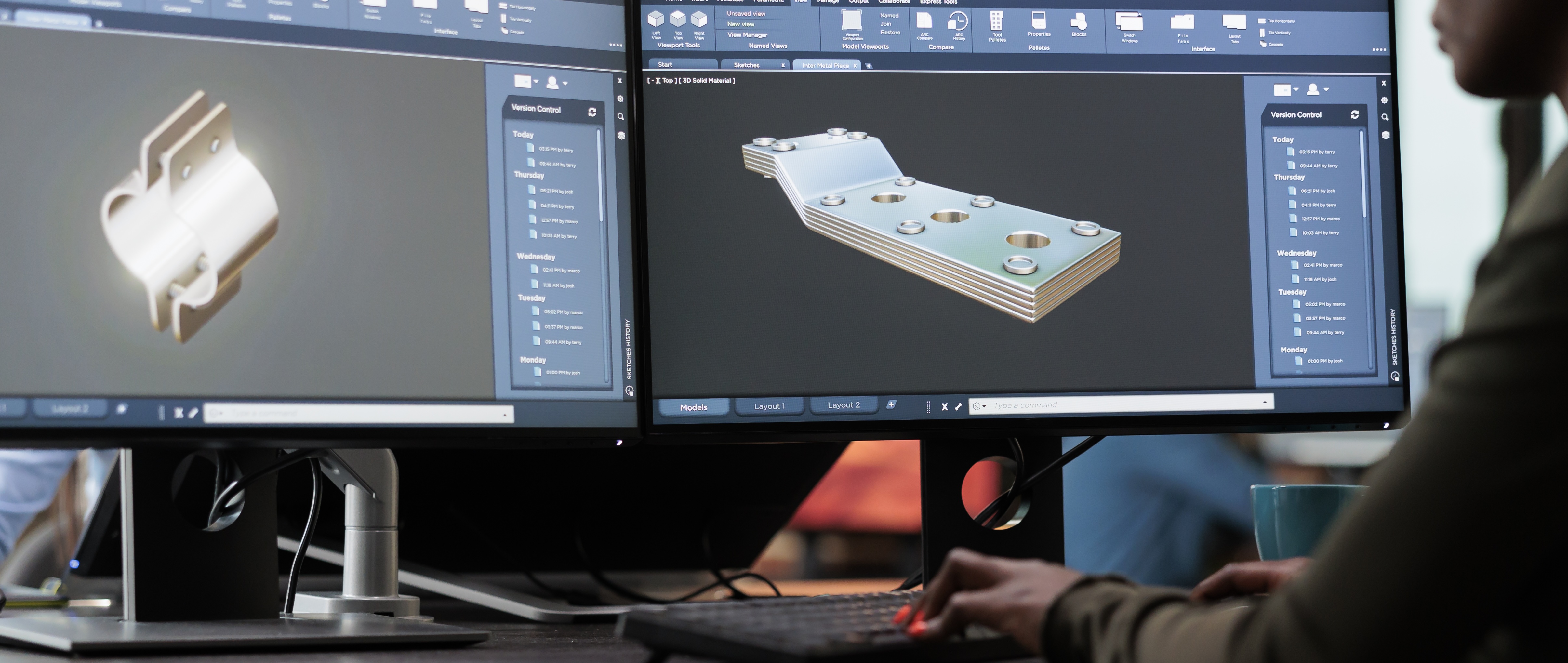
Our engineers thoroughly review every design to ensure it’s optimised for manufacture. We also use SolidWorks for advanced calculations like stress, tolerances, potential distortion, even speed, so adjustments can be made before production. This ensures everything is chosen for a bespoke extruded aluminium product that doesn’t just work, but excels.
Here are some key considerations to keep in mind when designing your aluminium profile:
Self-check questions to design an optimised aluminium profile
A CAD model can look perfect, but the real test is in production. To make sure your design will work efficiently and cost-effectively, ask yourself:
• Will it extrude reliably without distortion, excessive scrap, or premature die wear?
• How much machining time, tool changes, or custom fixturing will it demand?
• Are tolerances tighter than necessary in non-critical areas?
• Could differences in section thickness cause shade variation after anodising or lacquering?
• Do long lengths risk twist, bow, or tolerance creep that cause rework?
• Will uneven cooling in deep pockets or thin ribs create surface streaks or finish defects?
• Can features be simplified or integrated into the extrusion to reduce secondary machining?
• Can material be reduced while maintaining stiffness and strength?
• Is geometry driving up die cost or cooling time?
• Are machining faces accessible, clamp-friendly, and protected from cosmetic damage?
• Can finishing issues be minimised with better radii, drainage, and venting?
What DFM means for aluminium extrusion and machining
DFM aligns design intent with real-world constraints to make the entire chain—extrusion, machining and finishing—more efficient.
Extrusion focus:
• Improve metal flow with consistent wall thickness and sensible radii
• Reduce die stress and extend die life with balanced mass and symmetry
• Avoid sharp transitions that drive up cooling time or distort the profile
• Select appropriate alloys/tempers for strength, extrudability and finish
Machining focus:
• Design broad, flat faces and consistent datum edges for stable fixturing
• Place machining features (holes, slots, recesses) where cutters can access without awkward setups
• Protect visible surfaces from clamp marks and tool paths
• Match slots, hole diameters and depths to standard cutters and drills. Unusual geometries can cause poor tool performance, chatter, rapid wear, and even tool breakage
• Keep machining operations away from cosmetic faces wherever possible
Finishing focus:
• Avoid coating traps by designing drain and vent paths into the profile
• Minimise uneven section thickness that can cause shade variation in anodising or lacquering
• Protect cosmetic faces during handling and downstream processing
• Plan for consistent surface quality: radius transitions, smoother flow paths, and feature placement all impact anodised or powder-coated appearance
Key DFM rules to keep in mind when designing your aluminium profile
1. Wall thickness: keep it as uniform as possible; avoid sharp jumps. Many profiles work at ~0.8–1.5 mm depending on span and alloy.
2. Corner radii & fillets: generous internal radii (≥0.5–1.0 mm) protect the die and improve flow/finish.
3. Symmetry & mass balance: favour symmetric sections and even mass to reduce twist, bow and cooling issues.
4. Hollow vs solid: Solid sections have their place where bulk strength is required, but in many applications hollow profiles deliver better stiffness, stability and long-term cost savings. At ALUCAD, we often end up recommending hollows because they offer a clear performance advantage without driving up costs.
5. Tolerances: apply tight bands only where they affect fit/function of your final product; relax elsewhere to reduce cycle time and rejects.
6. Clamp & datum strategy: design flat faces and consistent datum edges for quick, repeatable fixturing.
7. Feature placement: slots, hooks, cable paths and some undercuts can be extruded instead of milled if designed correctly.
8. Length, cut & handling: plan saw cuts, deburr access and safe handling to protect visible faces.
9. Alloy & temper: choosing between alloys like 6060, 6061, 6063 and 6005A to balance strength, extrudability and finish. Alloy choice also affects tensile elongation at break and overall durability. The wrong alloy or temper can result in brittle profiles, poor strength or premature failure. Selecting the right alloy and hardening process ensures both performance and appearance.
10. Finish-aware design: avoid coating traps, ensure drain/vent paths, and design to minimise visible shade variation caused by differences in section thickness.
Design assistance: how ALUCAD ensures your bespoke aluminium profile works from the start
We provide design assistance for aluminium extrusion and machining optimisation to remove avoidable complexity that increases time and costs. If your team hasn’t considered every DFM point along the way, we will. Every design we review is checked against the principles above to make sure it functions, finishes and performs as intended efficiently, consistently and cost-effectively.
If your “finished” design is driving cost, lead time or waste, it can almost certainly be improved. With decades of expertise in manufacturing bespoke extruded aluminium products, we can ensure your custom aluminium profile performs better for less. Find out how we can help you improve your aluminium profile design.
